
Attitude Estimation - Aerodynamic Decelerator Systems Laboratory
Attitude Estimation
The so-called pose estimation problem, i.e. when in addition to a 3D position estimation we need to solve for an attitude of the test article as well, is much more challenging as compared to estimating just the 3D position. There are several algorithms based on the geometry-based features of an object to track exist. However, this specific application is unique in a sense that the payload itself resides in a very small box (maybe 30 pixels by 40 pixels out of a 240x320-pixel frame), has very little distinctive features (texture) on it, and, on top of that, there are huge compression artifacts. Nevertheless, several algorithms have been tested and software allowing to resolve the pose estimation problem (if the location of the multiple points is known) has been developed. The developed algorithms were built around either POSIT (Pose from Orthography and Scaling with Iterations) or SIFT (Scale-Invariant Feature Transform) software.
Within this research effort, it was found that if three or more payload’s features with the known geometry can be unambiguously determined (extracted from each frame), then pose estimation becomes possible (the created Simulink model, using the POSIT-derived algorithm originally developed by Daniel DeMenthon, is shown in Fig.L). Specifically, it was shown that for the four non-coplanar points this algorithm works fairly well. Obviously, the larger the base (distance) between these features, the more accurate results will POSIT (or any other) algorithm produce. Therefore, the corners of the payload are the best candidate points to track. As an example, Fig.M shows a sequence of the frames with four candidate points being chosen on each frame (manually).
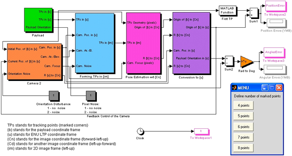
Figure L. The developed software based on the DeMenthon’s algorithm.
Figure N presents the results of processing the sequence of the frames shown in Fig.M by the model of Fig.L. No IMU/GPS data were available for this airdrop to compare the obtained results against, but qualitatively they look quite reasonable. Figure L represents the outputs of the model when applied to some simulated payload with attitude and pixel noise. As seen, the model performs very good assuring the Euler angles estimate error of less than half-a-degree. What is also important is that since the algorithm solves the complete pose estimation problem (not just attitude estimation), the ground camera knows precisely where to look for the payload at the very next moment (there is an active feedback loop in Fig.L). It results in keeping the payload in the center of the camera frame all the time ensuring the best performance possible.
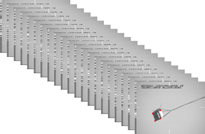
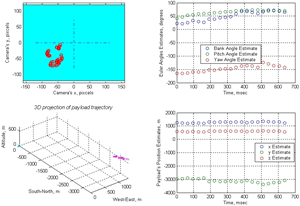
Figure M. Digitized video sequence. Figure N. The results of real data processing.
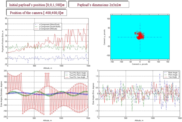
Figure O. Processing data from a virtual (emulated) payload.
To summarize, the POSIT-based algorithm exhibits a very good performance. The only problem is with having four non-coplanar corners of the payload in the camera’s field of view all the time. Even if multiple cameras look at a descending payload from three or four different directions, it is not possible to see four non-coplanar points by at least one camera all the time. There are periods of uncertainty, when only three (planar) points are observed by each camera. Firstly, it implies that the algorithm should include some filtering to predict a position (movement) of each point, so that it could be handed to the next camera to assure that is has a complete four-point constellation. Secondly, it suggests placing KTMs around the impact point evenly to minimize periods of uncertainty (which of course is quite problematic). That is why another approach, discussed next, was also investigated.
Another piece of software was build around the SIFT algorithm developed by David Lowe. Evolution Robotics ViPR™ technology (ViPR stands for visual pattern recognition) incorporated SIFT in their commercial products already and provided a reliable and robust vision solution that truly gives different electronic devices the ability to detect and recognize complex visual patterns. The idea of the SIFT approach as applied to payload pose estimation is that rather than tracking the 4+ non-coplanar reference points with the known geometry, we should somehow try to find much more distinctive invariant feature points in each frame. These multiple points could then be used to perform reliable matching between the subsequent frames.
Several hundred of such features (corners of an object or its unique texture patterns) are automatically extracted and stored in a database for each frame. Then a match within an extremely large set of possible candidates is fulfilled. The algorithm to select the correct candidate is similar to a voting mechanism - each feature votes for the candidate, which includes a similar feature. The correct candidate receives the largest number of votes since most of the features are in agreement. However, a single or a few votes might be incorrectly cast on wrong candidates. However, the likelihood that a large number of votes are cast on the wrong candidate is supposedly small, proving that the algorithm should be very reliable in selecting the correct match.
Figure P shows an example of multiple features found by SIFT for one of the frames shown in Fig.M. For this particular frame there were 69 automatically defined points (versus only four needed for the POSIT algorithm). Suppose one fourth of the found features will not find their matches on the subsequent frame – we should still have about fifty other matches to rely on. (Compare it to what would happen when a single point in a four-point scheme is missing or found incorrectly.)
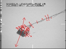
Figure P. One of the real airdrop frames featuring 69 scale-invariant key points.
However, as the following analysis revealed, the SIFT algorithm does not work as good as predicted with the poor-quality video aerial delivery systems testers are usually dealing with. Figure Q demonstrates that the hope that among those 69 features found on each image (Fig.P) the majority would find their match on the subsequent images did not prove true. On the contrary, less than one fourth of the found features finds their matches on the subsequent frames. To this end, Fig.Qa compares Frame 1 vs. Frame 2 (taken within 1/30=0.03sec). It shows only 17 matching key points. The comparison of Frame 1 and Frame 3 (2/30=0.07sec apart) reveals as little as 7 matching key points (Fig.Qb). Frame 1 vs. Frame 4 (3/30=0.1sec) yields 5 matching key points (Fig.Qc), and Frame 1 vs. Frame 8 (7/30=0.23sec) – a single matching key point (Fig.Qd). In just eight frames (about a quarter of a second apart) there is no match at all! Moreover, the matching points found on the further-apart frames are not necessarily show up on the closer-apart frames, i.e. there is no consistency.
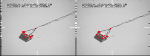
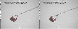
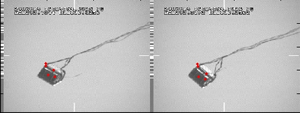
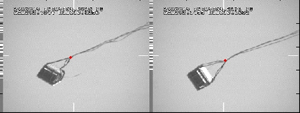
Figure Q. The key feature matches on the subsequent images: Frames 1 and 2 (a), 1 and 3 (b), 1 and 4 (c), 1 and 8 (d).
The same algorithm was applied to process video data from the airdrop with supposedly more distinctive patterns on the payload (different-color square plates were attached to each side of payload as shown in Fig.R). Moreover, the camera resolution was doubled as well featuring the 640pixel x 480pixel frames instead of the 320pixel x 240pixel frames as in Figs. P and Q. Unfortunately, these efforts were not repaid completely. The number of scale-invariant points for each frame (Fig.S) turned out to be about the same as before (compare it with Fig.P). Fortunately, the matching between the subsequent frames in this case was slightly better (27, 18, 13, and 7 points in Fig.Q compared to 17, 7, 5 and 1 in Fig.Q). This allowed estimating the attitude of payload more or less accurately and reliably for the entire airdrop.
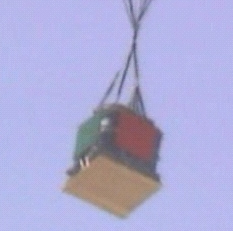
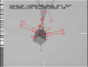
Figure R. Payload with more distinctive features. Figure S. Marked payload’s image featuring 67 scale-invariant key points.
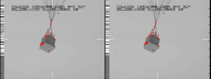
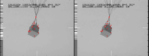
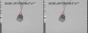
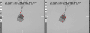
Figure T. The key feature matches on the subsequent images: Frames 1 and 2 (a), 1 and 3 (b), 1 and 4 (c), 1 and 8 (d).
The original algorithms developed within this research effort back in the early 2000's were gradually improved and finally converted into a very robust software package used in a variety of applications.