
Position Estimation - Aerodynamic Decelerator Systems Laboratory
Position Estimation
The common method of video scoring is labor-intensive since no autonomous tracking capability currently exists. After an airdrop, during which two to six fixed-zoom ground cameras record the flight, each video is manually "read" for determining a payload position in the camera frame coordinates. This is accomplished frame by frame, with the video reader clicking on a pixel that represents a visual "centroid" of payload. Each video frame has a left-edge bar code with the azimuth, elevation and UTC stamp, so all these data for each frame is stored automatically as the operator clicks on a chosen pixel. When the videos from multiple KTM locations are processed, a regression analysis is executed to determine a position of a test article in three dimensions (30). The payload position can then be numerically differentiated (and smoothened) to get an estimate of a 30 velocity vector. Accounting for the air column data obtained using the drop sonde usually released prior to the actual airdrop allows getting an unbiased estimate of test article performance.
The automated capability of accurately acquiring TSPI would hasten processing of each video by autonomously tracking the payload once initialized. Moreover, multiple objects in the cameras' field of view could simultaneously be processed allowing obtaining much richer data. Then, data from multiple cameras can be 'fused' together to obtain TSPI in a usual manner.
The development of such autonomous capability (standalone TSPI retrieving system) should obviously address the following two independent problems. First, it should process video data itself with the goal of obtaining the frame coordinates of the certain point(s) on the test article, say payload's geometric center. Second, it should provide the most accurate solution of the position estimation problem assuming that information from two or more cameras situated around DZ is available.
The appropriate software to solve each of two problems has been developed and successfully tested in computer simulations and with the real airdrop data. When this project was conceived, video data processing was based on a piece of software developed by PerceptiVU, Inc., namely PerceptiVU Tracker to retrieve x-/y-offsets of the center of the test article from each frame. The PerceptiVU Tracker window with several drop-down option windows is shown in Fig.C. For the batch processing the operator encloses the test article to track into the appropriate-size box on the very first frame and then this item is being tracked all way down automatically.
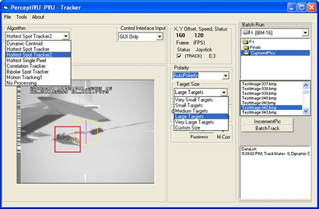
Figure C. Setting the options for the PerceptiVU Tracker.
Figure D represents an example of correcting video data (eliminating the corrupted lines, excluding spikes, and filling in dropouts) using the 128-point Welch FFT window, and an example of the processed data for three KTMs is shown in Fig.E.
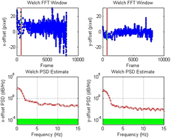
Figure D. Checking/correcting time histories of the x-/y- offsets.
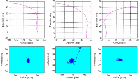
Figure E. Example of conditioned data for three cameras.
 of payload’s centroid, when its projection
  , i=1,…,N onto the image plane of N cameras is available. The positions
  of each camera in the local tangent plane (LTP), as well as their focal length, fi, azimuth,
  , and elevation,
  , are known.
 Obviously, each camera contributes with two nonlinear equations (written for the horizontal and vertical planes). Hence, to resolve for three components of vector  we need to have at least two cameras (N>=2). The more cameras record the airdrop and more evenly they are distributed, the more accurate position estimate we could get.
In this project, this problem was cast as a multivariable optimization problem: choose components of vector that minimize some compound performance index. This problem is solved at each instant of time within a Simulink model that employs the standard fminsearch function of MATLAB for unconstrained non-linear minimization (based on the non-gradient Nelder-Mead simplex method). The developed software proved to be very reliable and quite robust in handling both emulated and real airdrop data. Figure F shows the results of processing data shown in Fig.E. It also shows the results of the descent rate estimate. For this particular airdrop the GPS/IMU data were also available, so the comparison with exact data demonstrates a perfect match (with an average error of less than 2m that corresponds to the cameras’ pixel size).
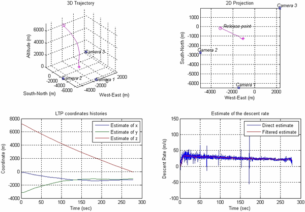
Figure F. Position and descent rate estimation using data of Fig.E.
Figures G and H demonstrate another example when data from six cameras were available. The top-left plot in Fig.G presents a bird’s eye view of the KTM constellation around the release point (radial lines show the direction to the test article at the release (solid lines) and impact points (dashed lines)). The bottom plot depicts the Az/El data for all six cameras. The top right plot demonstrates the estimate of the geometric dilution of precision (GDOP), i.e. the maximum accuracy that could be possibly achieved (based on the cameras’ pixel resolution). Figure H shows the result of processing these six-camera data.
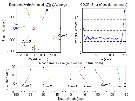
Figure G. Results of video data processing for the six-camera cargo airdrop.
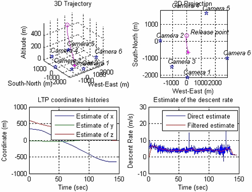
Figure H. Position and descent rate estimation for the cargo airdrop presented in Fig.G.
It should be noted that algorithms developed within this research effort in the early 2000’ and used in a variety of different projects since then are compatible with the TrackEye software package developed for motion analysis a decade later (www.imagesystems.se). As applied to the aerial payload delivery system position estimation this latter package assumes manually building a data flow model like the one shown in Fig.I, where each block represents a certain procedure applied to the input stream. For instance, Fig.J features an example of the point tracking settings block and Fig.K shows examples of the TSPI analysis output.

Figure I. Example of the TrackEye TSPI model.

Figure J. Example of the tracking settings block.
a)  b)
b) 
Figure K. Example of the TDSI solution for a specific airdrop (a), and position estimation error time history (b).
For the purpose of TSPI the TrackEye software package relies on tracking algorithms that are somewhat similar to those of PerceptiVU Tracker (cf. Fig.C and Fig.J).
Being a versatile package TrackEye assumes a lot of manual operations before a TSPI solution could be obtained. The goal of the NPS research however was creating a fully automatized software package specifically tuned for obtaining aerial payload delivery system TSPI solutions, and as opposed to TrackEye the NPS-developed software package enables a batch processing, so that a solution for each airdrop could be obtained in a matter of minutes rather than hours and days.